Loading... Please wait...
Have Questions? Call Us: 1-800-323-2282
Since 1974, Your Single Source for HVAC, Controls, and Electromechanical Components.

- Home
-
Products
- Batteries & Chargers
- Bundling and Securing
- Cables
- Circuit Protection
- DIN Rail & Track
- Electronics
- Enclosures
- Flashers
- Fuses
- Identification & Labeling
- Lighting & Lamps
- Miscellaneous Products
- Networking
- Plugs & Sockets
- Power Supplies
- Pushbuttons
- Relays & Sockets
- Screws & Hardware
- Sensors
- Terminal Blocks
- Tools & Accessories
- Transformers
- Wire & Cable
- Featured Products
- Authorized Brands
- Shipping & Returns
- Customer Service
- About Us
- Contact Us
- Blog
Shop by Category
Shop by Brand
Our Newsletter
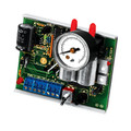
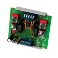
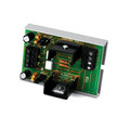
ACI ATP Sensor Interface Device

)
List Price:
Your Price:
$78.00
(You save $66.00)
Call for Volume Pricing
(800) 323-2282
Brand:
Weight:
0.08 LBS
Shipping:
Calculated at checkout
Product Description
ATP Version 1 converts an analog signal into a digital pulse output signal. The user can select eight standard analog input ranges to the ATP by changing jumper shunt positions. To select the output pulse range, the ATP has an eight position DIP switch. The output pulse is continuous with a one second off between pulses. ATP Version 2 operates the same except when the analog input falls at or below 10% of the input signal range, no pulse output occurs. This allows for a true "OFF" setting for solid state relays controlling electric heat. The ATP has two timing ranges, standard and custom selectable. The standard mode, selected by DIP switch 1 "ON" and proper setting of switches 2 and 3, allows four different timing ranges . Switches 4 through 8 are not active when switch 1 is on. Standard Mode: SolidyneTM .023 to 6 seconds AndoverTM .1 to 25.5 seconds JohnsonTM .02 to 5 seconds NovarTM .59 to 2.93 seconds The Custom Mode allows for 128 pulse timing ranges. With dip switch 1 "OFF", switches 2 through 8 select the timing values. One or more switches can be selected. Refer to the chart on the Installation Instructions. For example, if switch 2 and 3 were "ON" (50 milliseconds + 100 milliseconds), each A/D step would equal 150 milliseconds (ms). Let us assume an analog input signal of 0-10V. With switches 2 and 3 "ON" the total of 150ms would equal 0 VDC. We can see on the chart that at 10 VDC, the values for switches 2 and 3 "ON" are 12.8 seconds and 25.6 seconds respectively, totaling 38.4 seconds. Thus the pulse width output range is 150ms to 38.4 seconds. All switches off equal 25ms per step.